
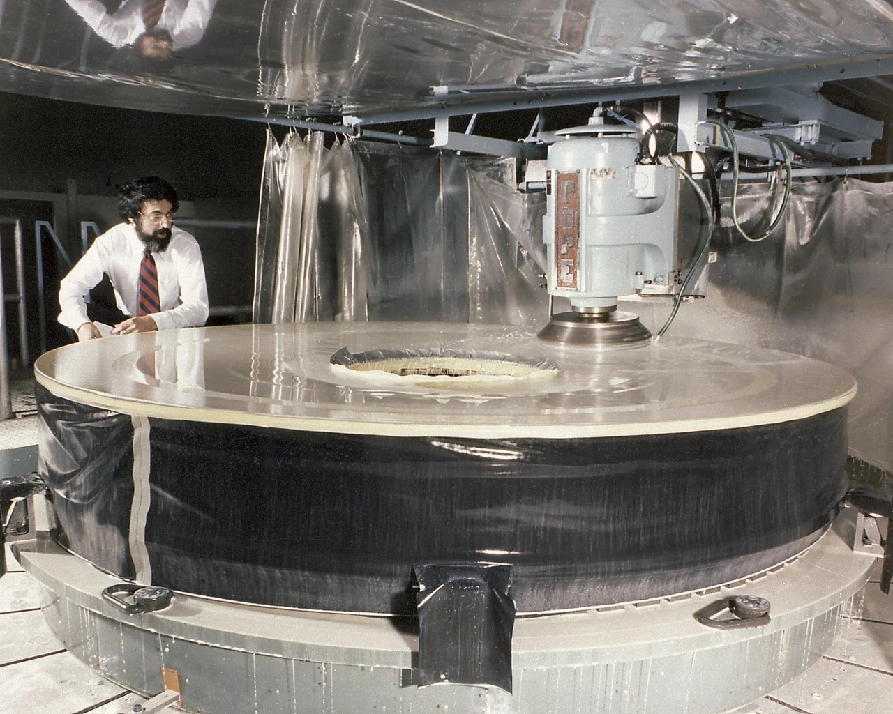
Hubble’s first images were blurred because its primary mirror had been polished to the wrong curve. Near the outer edge, the surface departed from the intended shape by about 2.2 micrometers. That was enough to prevent light from a distant star from coming to the same focus.
In December 1993, astronauts installed optics that compensated for the error farther along the light’s path. The original mirror stayed in place. Understanding that repair starts with a distinction: a mirror can be extremely smooth and still have the wrong shape.
What was wrong with Hubble’s mirror?#
Hubble collects light with a primary mirror 2.4 meters across. Light reflects from this large mirror to a smaller secondary mirror, then passes through a hole in the primary on its way to the instruments. The curves of those reflecting surfaces determine where the light goes.
Hubble’s primary mirror was too flat toward its outer edge. This was a gradual error in its overall curve, not a scratch, crack or rough patch. NASA’s account of the first servicing mission gives the deviation as 2.2 micrometers, or 0.0022 millimeters.
The scale is difficult to picture because the mirror looks perfectly ordinary in a photograph. The manufacturing image above documents the hardware; it cannot show a deviation this small. Smoothness describes the texture of a surface. Optical accuracy also depends on whether that surface follows the intended curve.
How small is 2.2 micrometers?#
A micrometer is one millionth of a meter. The reported edge deviation was 2.2 millionths of a meter across an optic 2.4 meters wide. Their ratio is about nine parts in ten million. That comparison explains why an ordinary photograph cannot reveal the defect, but it is not a useful tolerance for deciding whether a telescope will focus sharply.
Light supplies a more relevant scale. A representative visible wavelength of 550 nanometers is 0.55 micrometer. The mirror's 2.2-micrometer surface departure is about four of those wavelengths. This is a scale comparison, not a calculation of Hubble's wavefront error: reflection geometry and the way the error varies across the mirror also matter.
The two scales explain the surprise. A departure that is tiny compared with a piece of hardware can still be large compared with the light that hardware must bring together. The diagram also keeps the separate 1.3-millimeter test-equipment error out of that comparison.
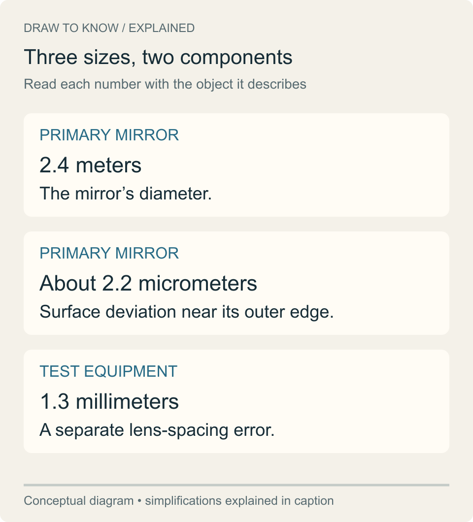
Image unavailable.
Three cards distinguish mirror diameter, mirror surface deviation and a separate error in the test equipment.
Why did such a small error blur a star?#
Consider light from just one distant star. Rays reaching different regions of a correctly shaped mirror should contribute to the same sharply focused image. With Hubble’s faulty curve, light from the outer regions and light from nearer the center came to focus at different positions. This effect is called spherical aberration.
The star did not simply disappear. Its image had a concentrated core surrounded by a much broader halo. Spreading light into that halo made fine detail harder to distinguish. Moving an instrument to a different focus could not bring all of those rays together at once.
A useful thought experiment is to slide a screen along the light path. For ordinary defocus, moving the screen toward the correct focal plane can sharpen the image. With spherical aberration, different zones of the optical system prefer different focus positions. There is no single screen position that makes every zone agree. The ray diagram shows that difference conceptually; it is not a reconstruction of the exact Hubble optical prescription.
Hubble still made useful observations before the repair, including science that could not be done from the ground. The problem was that its optical performance fell short of what the telescope had been designed to deliver.
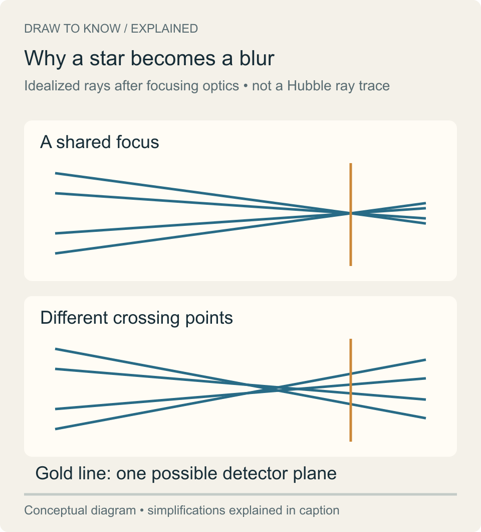
Image unavailable.
Two ray fans compare a common focus with rays crossing at different distances. A detector plane cannot capture every ray at one point in the second case.
How did the wrong curve pass its test?#
The mirror’s curve was checked during manufacture with an optical device called a null corrector. The test equipment itself had been assembled incorrectly. Investigators later found a lens-spacing error of 1.3 millimeters, so the test guided the polishing toward the wrong shape.
There are two different measurements in this story. The 1.3-millimeter error belonged to the testing equipment on Earth. The roughly 2.2-micrometer deviation belonged to the resulting mirror surface. They describe different parts of the chain of events and should not be used interchangeably.
After launch, both of Hubble’s imaging cameras showed the characteristic distortion. That pointed investigators toward the telescope optics shared by the cameras. NASA announced the problem on June 27, 1990. The investigation then traced the mirror’s shape back to its fabrication and testing equipment.
Sources: [1]
How did astronauts fix the view without replacing the mirror?#
Hubble was built to be serviced in orbit, with instruments that astronauts could remove and replace. During the first servicing mission in December 1993, the crew of space shuttle Endeavour installed two different solutions to the optical problem.
This work illustrates what the Shuttle's payload bay and working space made possible.
The Wide Field and Planetary Camera 2, or WFPC2, replaced the original camera. It carried its own corrective optics. Four small mirrors inside WFPC2, one for each camera channel, introduced a compensating error: where the primary mirror’s curve was too shallow, the corrective mirrors were curved too deeply. Together, the optical effects canceled.
COSTAR, short for Corrective Optics Space Telescope Axial Replacement, served three other instruments. It deployed small mirrors into their light paths, including the path to the Faint Object Camera. WFPC2 did not depend on COSTAR; it had its own correction.
The familiar description of “glasses for Hubble” captures the idea of compensating for an optical problem. The hardware was installed inside the telescope, where instruments received the light. Astronauts did not reshape the primary mirror or fit a giant lens over the front opening.
Why correction worked farther along the light path#
The telescope's job is to deliver an organized pattern of light to an instrument. A predictable distortion introduced at one surface can be compensated by suitably designed optics elsewhere in the system. That is why the solution could be installed with the instruments rather than by regrinding the primary mirror in orbit.
The corrective surfaces had to match the particular error. Simply adding more magnification would have enlarged the blur. The correction instead changed how the light converged, concentrating more of a star's light where it belonged. NASA describes four corrective mirrors inside WFPC2, one in each channel, while COSTAR placed corrective mirrors in the paths to other instruments.
This distinction matters when reading the servicing story. WFPC2 and COSTAR were parallel solutions for different destinations of the telescope's light. They were not two stages through which every image passed. The routing diagram shows their roles without implying that all instruments operated through one shared corrective box.
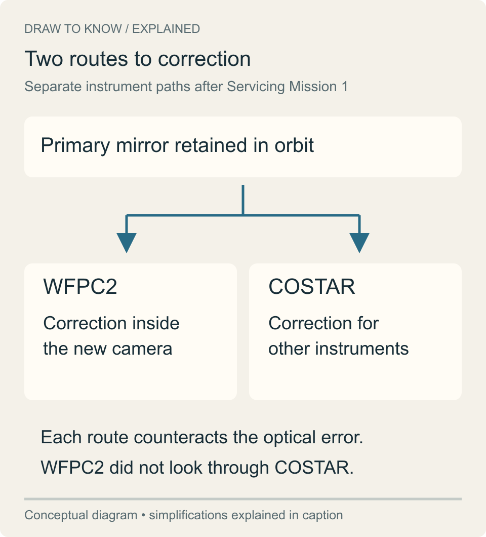
Image unavailable.
A common primary mirror branches into two independent correction routes: internal WFPC2 optics and COSTAR serving other instruments.
What do the before-and-after pictures actually show?#
The paired images below show Melnick 34 observed with Hubble’s Faint Object Camera. Before COSTAR, a broad halo surrounds the star’s bright center. After correction, the light is much more tightly concentrated. Because these are observations of the same target with the same camera, they give a clear visual demonstration of the correction.
This published comparison is evidence of the change in image quality, not a ruler for measuring the mirror’s 2.2-micrometer error. A numerical assessment of optical performance requires the underlying measurements and calibration, beyond what a reproduced picture alone can establish.
Another widely shared comparison shows the galaxy Messier 100 in three panels. ESA/Hubble identifies them as WFPC1 in 1993, WFPC2 in early 1994, and WFC3 in 2018. The middle panel shows the result after the first repair. The right panel also includes a later camera upgrade, so it should not be presented as simply the immediate “after” image from 1993.
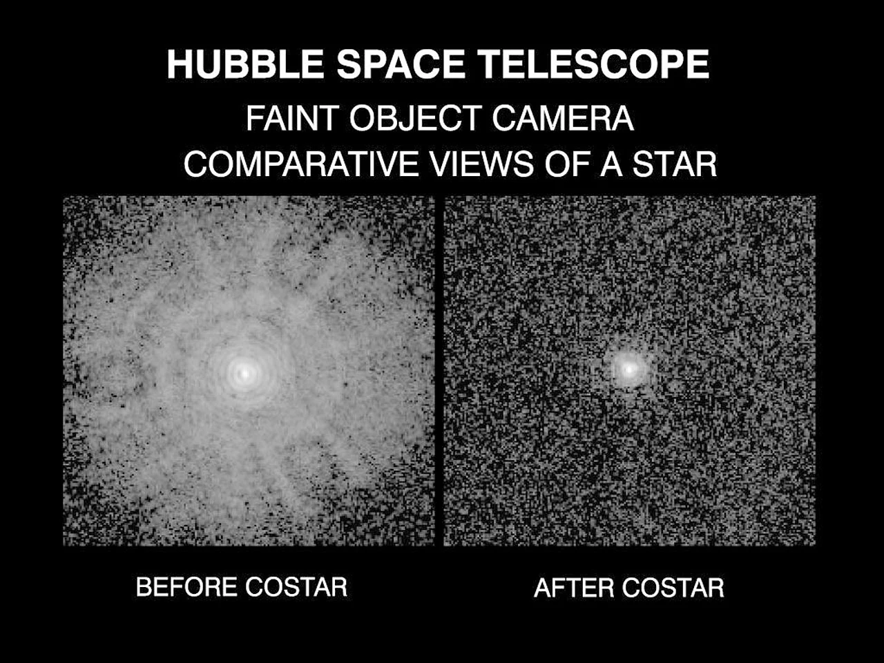
Image unavailable.
Two Faint Object Camera images of Melnick 34: a broad halo before COSTAR at left and a much tighter star image after COSTAR at right.
What happened to the correction afterward?#
Later instruments incorporated their own corrective optics. As those instruments replaced the originals, COSTAR was no longer needed. Astronauts removed it in 2009, during the final servicing mission, and returned it to Earth.
The sequence matters: Hubble’s mirror was made with the wrong curve, the error became apparent after launch in 1990, and the 1993 servicing mission compensated for it inside the instrument paths. Later upgrades continued that approach. The repair restored a sharp view while leaving the original primary mirror in place.
Keep exploring
Sources & further reading
Follow the original research, records, and explanations behind this story.
- Hubble’s Mirror Flaw NASA Science
Investigation, the 1.3-millimeter test-equipment error, the 1979 photograph and the Melnick 34 comparison.
- Servicing Mission 1 NASA Science
The 2.2-micrometer mirror deviation, the December 1993 mission, and the separate roles of WFPC2 and COSTAR.
- Hubble’s Optics NASA Science
The light path, surface smoothness and useful science before correction. For the numerical deviation, this article follows the specific Servicing Mission 1 account.
- The Camera That Saved Hubble NASA Science / Jet Propulsion Laboratory
How the four corrective mirrors inside WFPC2 compensated for the primary-mirror error.
- Messier 100 shows improvements of Hubble ESA/Hubble
The original three-panel galaxy comparison and the dates and instruments needed to interpret it correctly.
See the story in motion
Watch our illustrated video, then explore another question below.
Watch on YouTubeFollow the thread